Continuity, wiremap and the split pair nobody sees
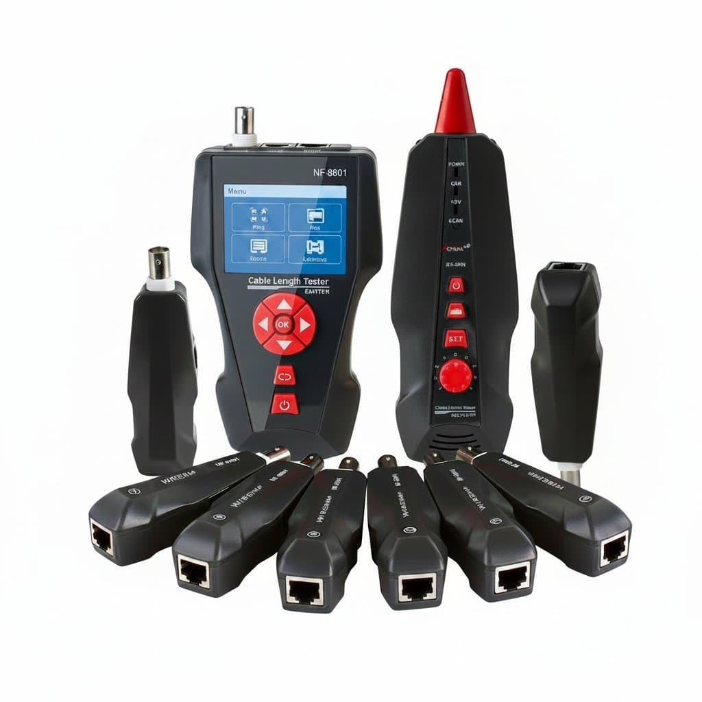
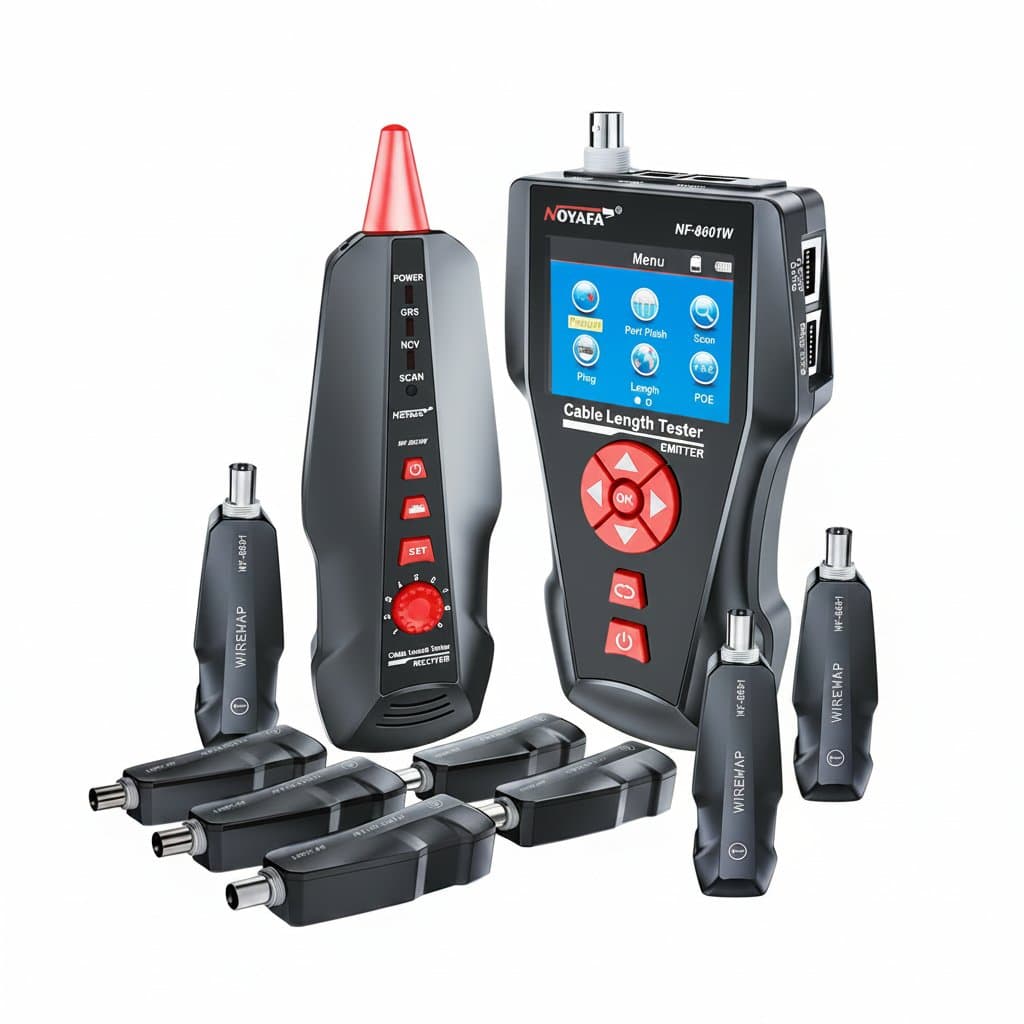
The basic job is a wiremap: confirming pin 1 at one end reaches pin 1 at the other, and that nothing is open, shorted or crossed. A cheap tester with a main unit and a remote does this by lighting eight LEDs in sequence, and for a patch lead it is genuinely all you need.
What that test cannot see is a split pair. If two wires are swapped between pairs, every pin still connects to the right pin, so the LEDs march through in order and the tester says the cable is good. Electrically it is not: the twists no longer cancel, crosstalk rises, and the link fails at speed while passing a continuity test. Only a tester that measures the pairing rather than the pins will catch it, which is the single clearest reason to spend more than the price of a basic LED unit.
Length and distance to fault
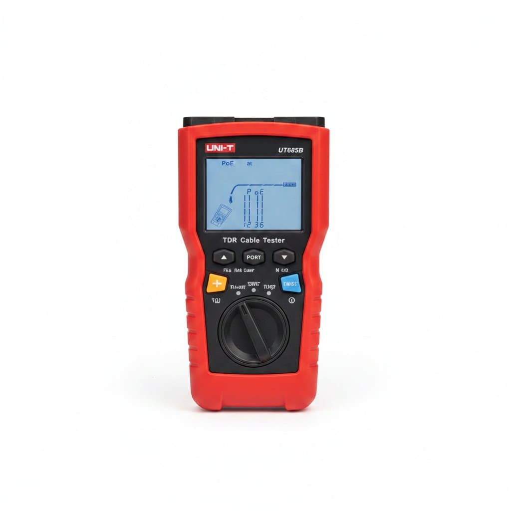
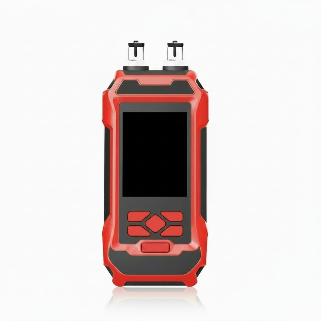
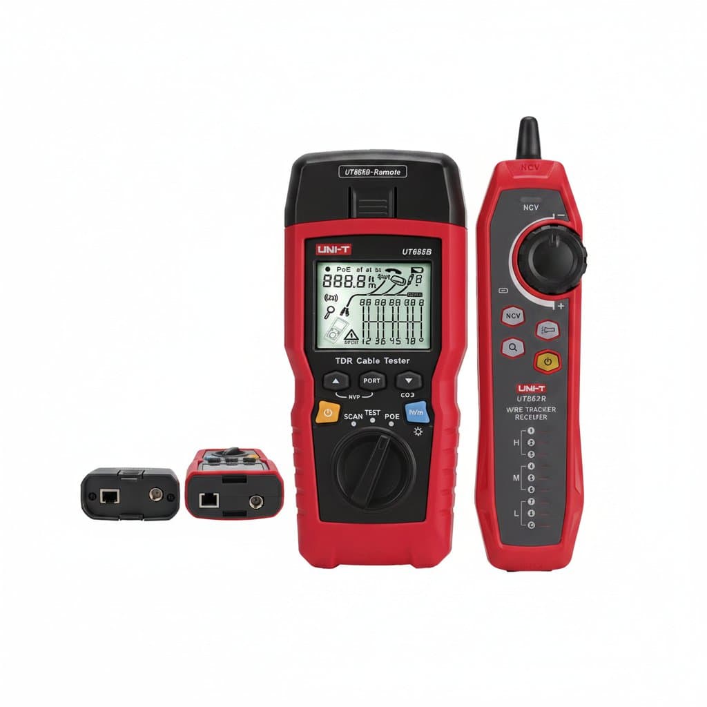
Time-domain reflectometry sends a pulse down the cable and times the reflection that comes back from the far end or from a fault. The instrument converts that time into a distance, which gives you both the cable length and, on a broken run, roughly how far along the break sits. On a building full of unlabelled cable that turns a guessing game into a measurement.
The figure depends on the cable, not just the clock. Signals travel at a fraction of the speed of light that varies by construction, and testers express this as a nominal velocity of propagation. Leave the NVP on the wrong cable type and the length reading is proportionally wrong, so set it for the cable you are testing or calibrate against a known length before trusting the number.
| Class | Answers | Does not answer |
|---|---|---|
| Continuity / wiremap | Is each pin connected, is anything open, shorted or crossed | Split pairs, length, whether it will run at speed |
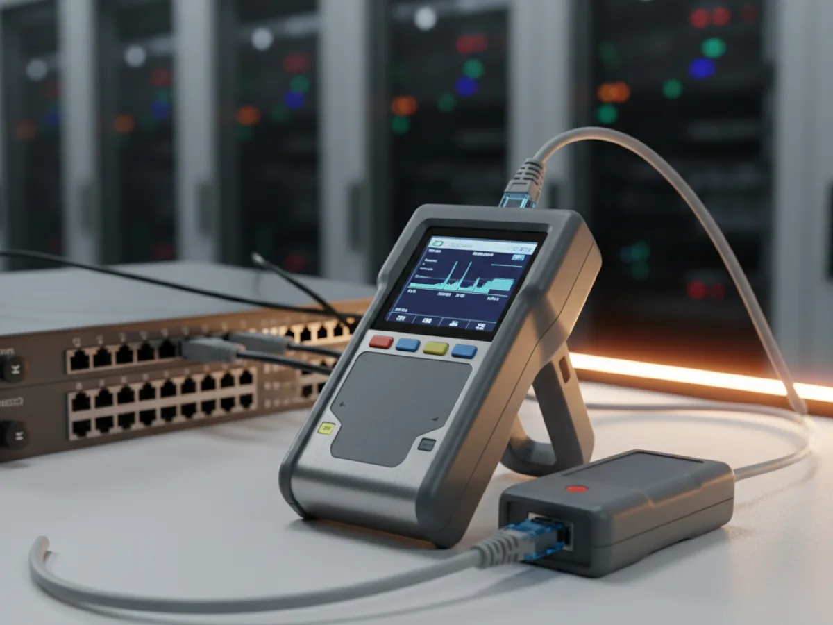
| Qualification tester | Wiremap, length by TDR, distance to fault, PoE presence | Formal compliance with a cabling standard |
| Tone generator and probe | Which cable in the bundle is this one | Anything about whether the cable is good |
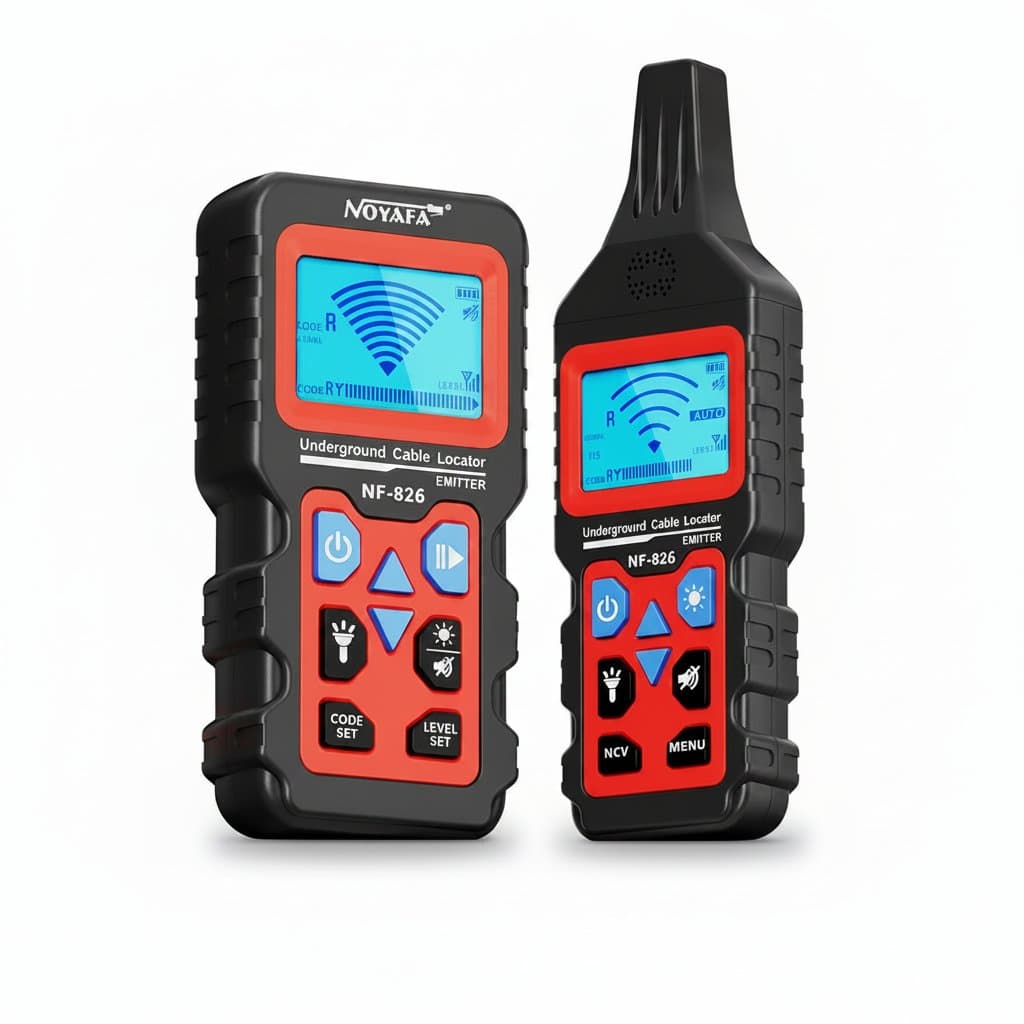
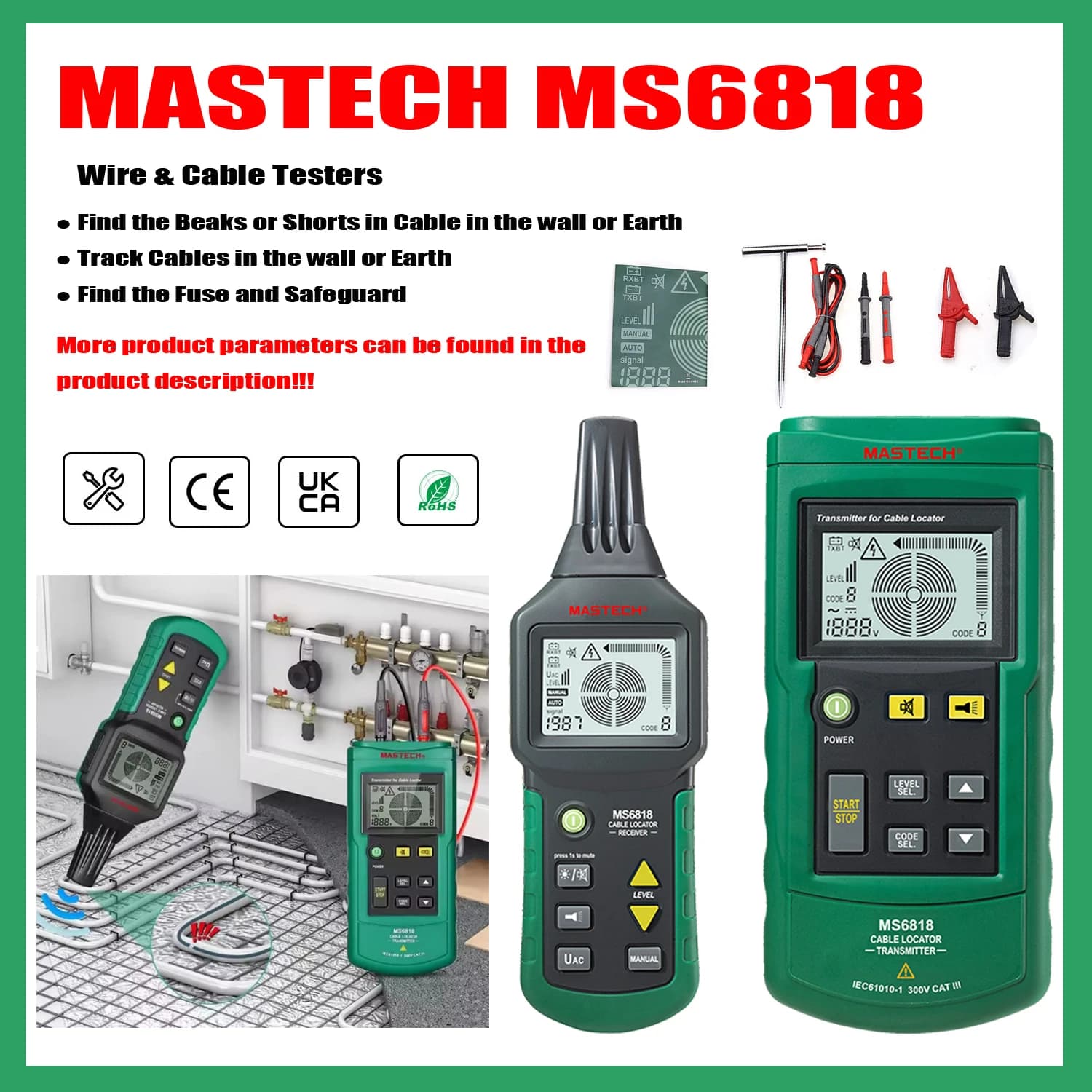
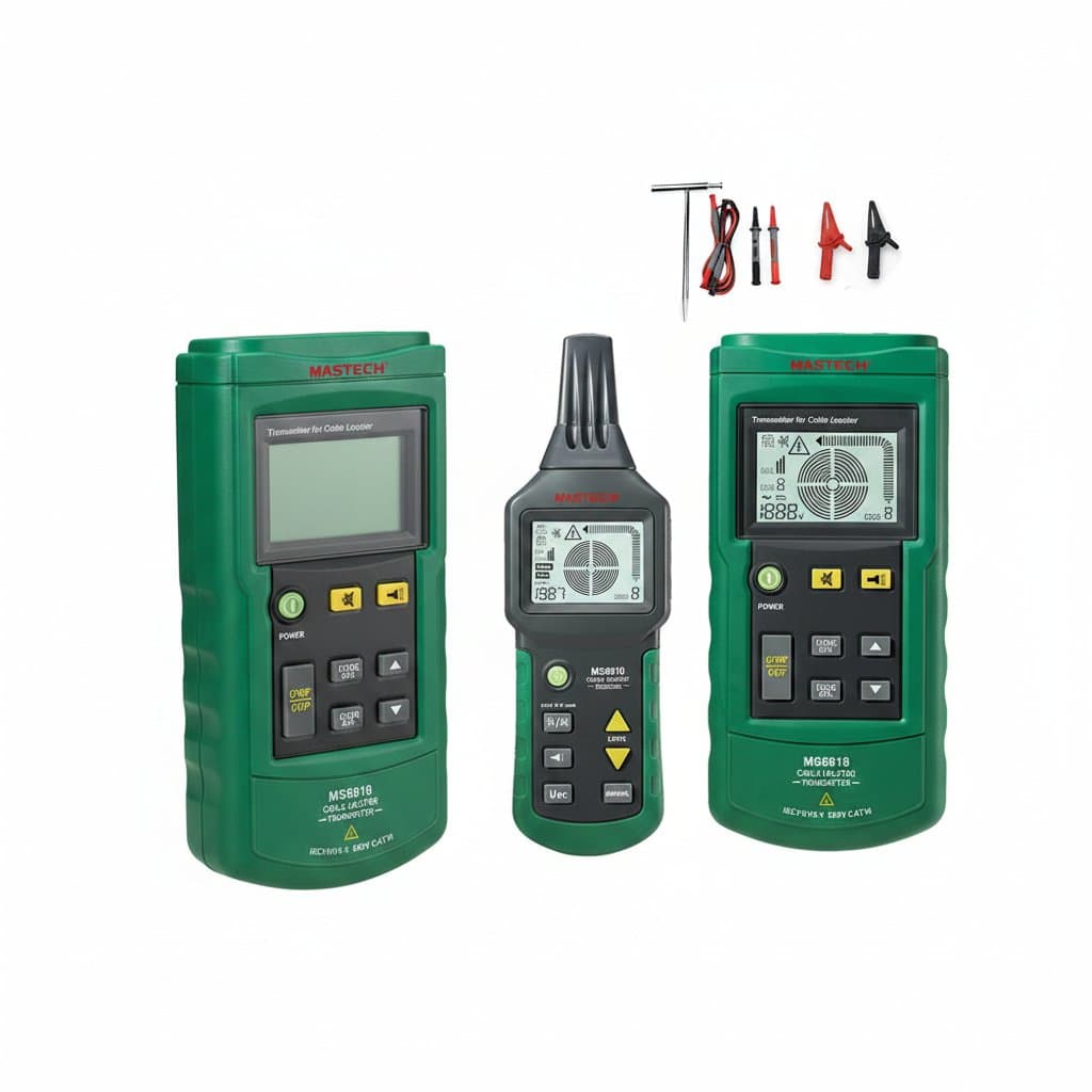
| Cable locator | Where a buried or hidden run goes, and how deep | The condition of the conductors |
PoE checks before you plug the camera in
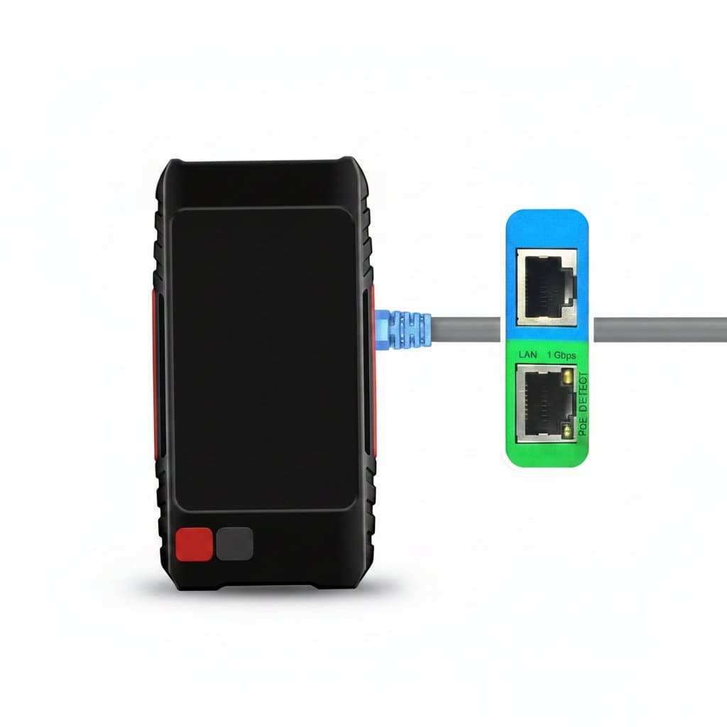
Power over Ethernet puts DC on the same cable as the data, and a tester that reports it saves a lot of arguing about whether the fault is the camera or the switch. The useful readout is which pairs are carrying power and roughly what voltage is present, because that separates a switch port that is not delivering power from a device that is not accepting it.
Test at the far end, at the point where the device plugs in, not at the patch panel. Voltage drop over a long run with thin conductors is exactly the failure that only shows up at the device, and a reading taken next to the switch will look perfectly healthy while the camera at the end of the run keeps rebooting.
Tracing and locating buried runs
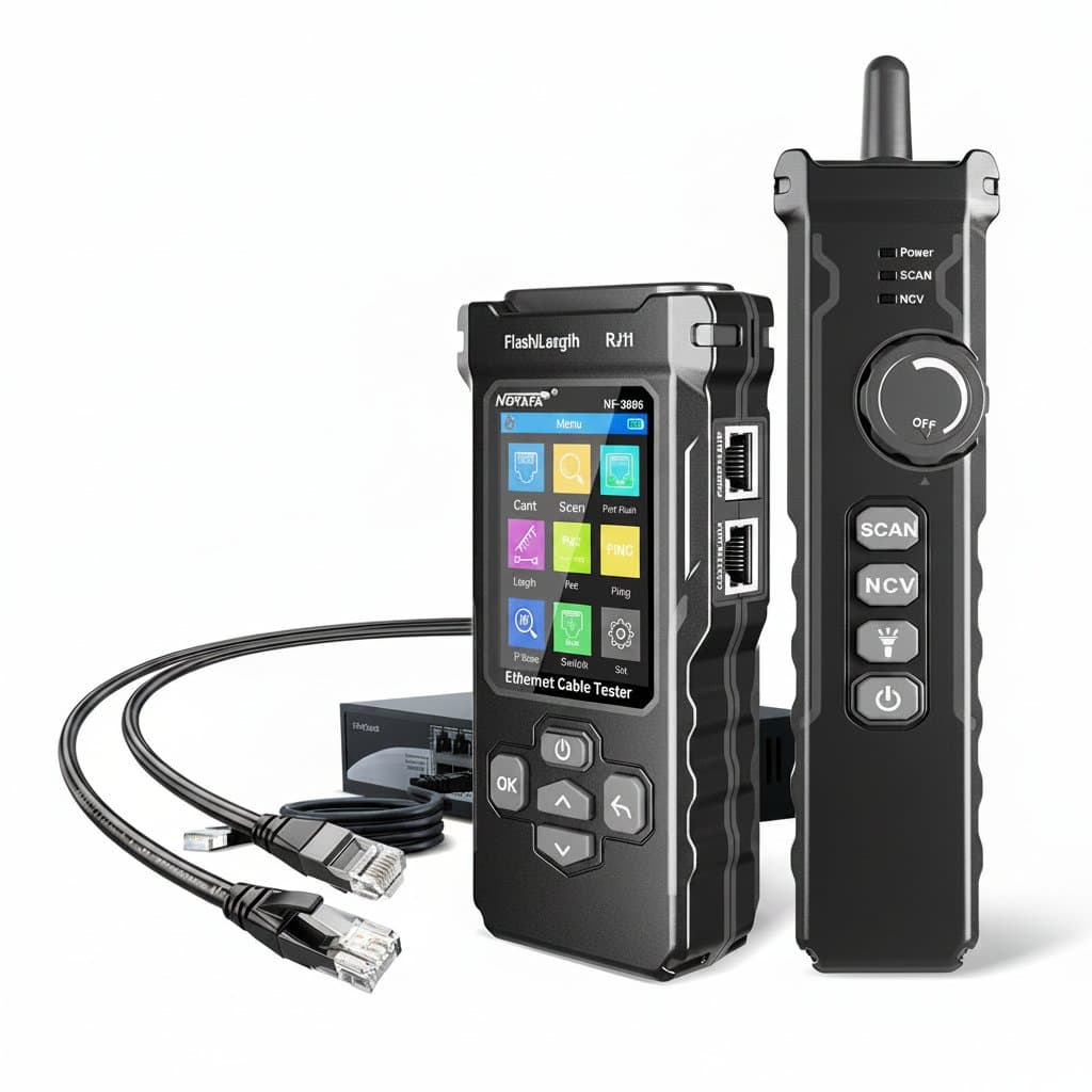
Tracing is a different job from testing. A tone generator clips onto the pair and injects a signal; an inductive probe then finds that signal through insulation, plasterboard or a bundle of a hundred identical grey cables. It tells you nothing about whether the cable works, only which one it is.
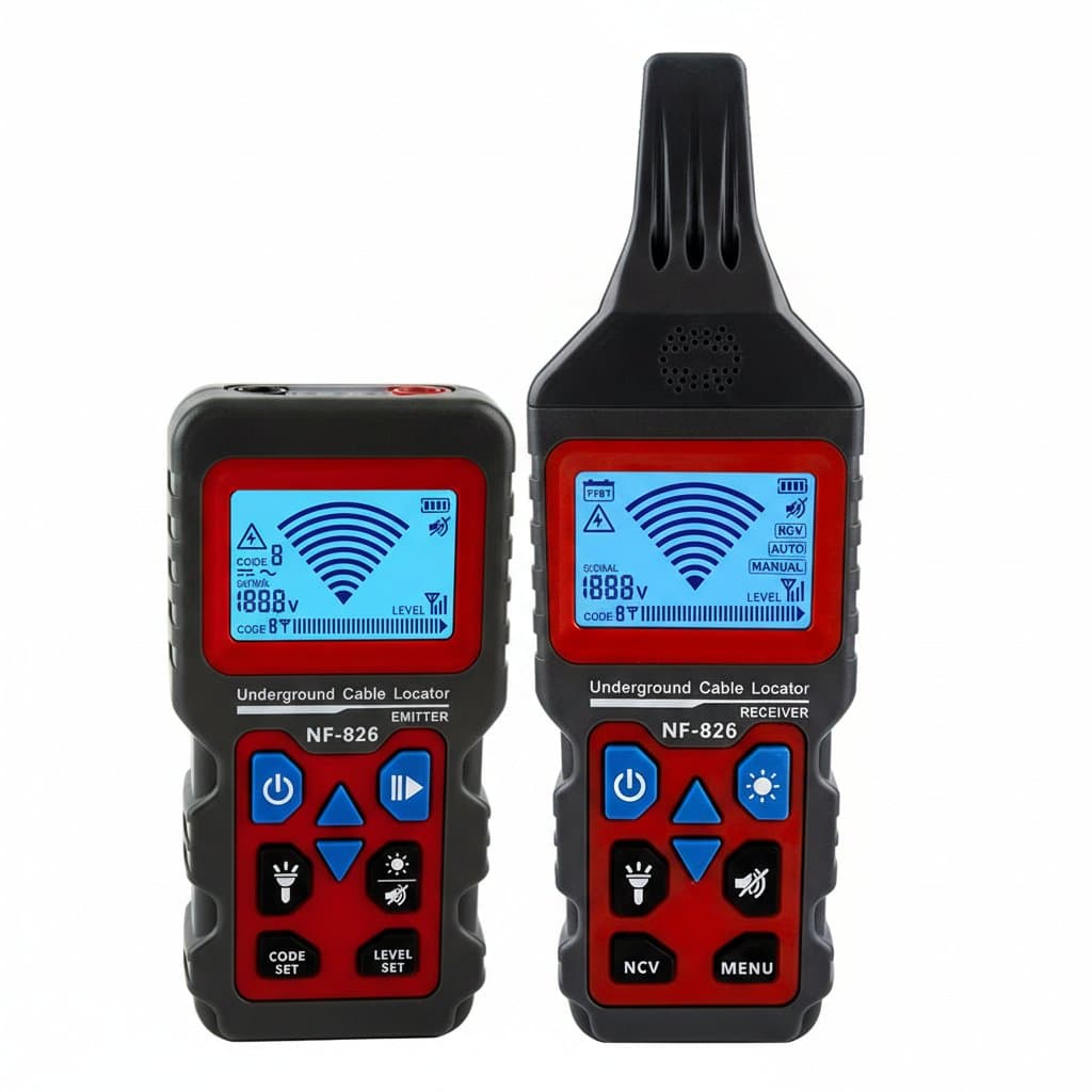
A cable locator scales the same idea up for buried services. A transmitter energises the line and a receiver walks the route above it, giving position and an estimated depth. Depth figures are an estimate rather than a survey and they are affected by nearby metalwork, so treat them as a guide to where to dig carefully, never as permission to dig confidently.