
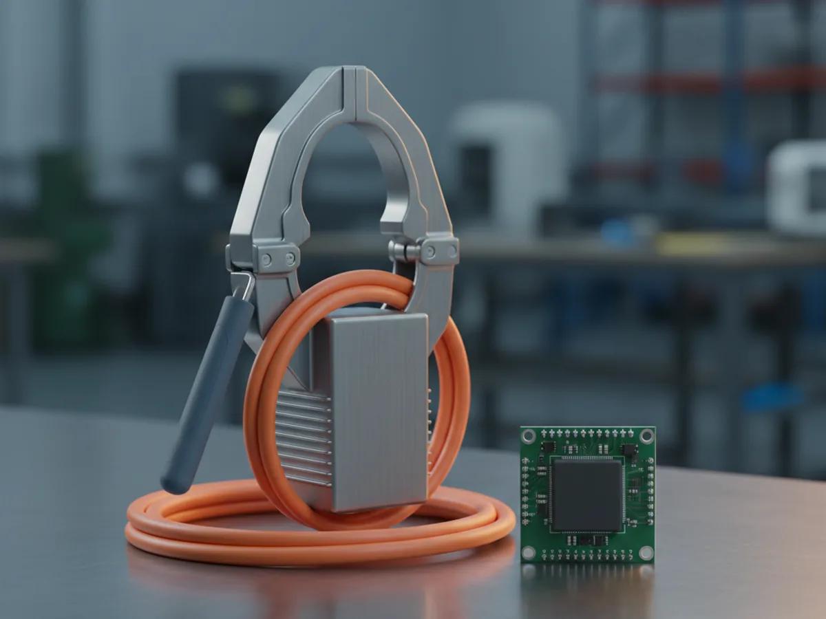


Current transformer or Hall effect module
A current transformer is a coil around the conductor. The magnetic field from the current in the primary induces a proportional current in the secondary winding, and because that field only exists while the current is changing, a CT cannot see direct current at all. It needs no power supply, which is why it is the default for mains monitoring and submetering.
A Hall effect device measures the magnetic field directly using a semiconductor element, so it reads steady direct current as happily as alternating. That makes it the choice for battery systems, solar strings, motor drives and anything on a DC bus. The trade is that it needs a supply, it has an offset that drifts a little with temperature, and it is generally less accurate than a decent CT on pure AC.
Sensors of both kinds appear as split core and solid core. A split core clamps around a cable that is already installed and is the only practical option on a live board you cannot take down. A solid core has the conductor threaded through it, which gives better accuracy and a lower cost but means breaking the circuit to fit it.
| Current transformer | Hall effect module | |
|---|---|---|
| Measures DC | No | Yes |
| Needs a supply | No | Yes |
| Typical use | Mains monitoring, submetering | Battery, solar, motor drives |
| Fitting | Split core clamps on a live cable | Usually inline or board mounted |
| Watch out for | Never open circuit the secondary | Offset drift with temperature |
Never leave a current transformer secondary open
This is the one genuine hazard in the category and it is worth stating plainly. A current output CT, the type quoted as something like 100 A to 50 mA, relies on its burden being connected. The primary current is fixed by the load on the circuit, not by the CT, so if you break the secondary circuit while current is flowing the transformer tries to drive that current into an open circuit and develops a very high voltage across the terminals.
The practical rules follow from that. Short the secondary terminals together before disconnecting anything downstream. Never fit a fuse or a switch in a CT secondary. If a monitoring device is being swapped out, short the CT first and leave it shorted until the new one is wired in.
Voltage output types, such as the widely used split core sensors quoted as 100 A to 1 V, have the burden resistor built in and do not have this problem, which is one reason they are the easier choice for hobby and light commercial monitoring. Check which you have before assuming either way, because the two look identical from the outside.
Matching the output to the receiving equipment
Three outputs cover almost everything. A milliamp current output, typically 100 A to 50 mA, suits a meter designed to take a CT directly. A low voltage output such as 1 V or 333 mV full scale suits an analogue input or a monitoring board. A 4 to 20 mA loop output, which is what most units described as transducers provide, is the industrial standard for running a signal a long way to a PLC without noise pickup and with a live zero that distinguishes a real reading of nothing from a broken wire.
For microcontroller work the modules built around Hall effect chips give a voltage centred on half the supply, swinging up for current one way and down for the other. That centre point is the thing to calibrate, because it moves with supply voltage and temperature and an uncalibrated offset shows up as a permanent phantom load.
Size the range to the load, not to the breaker. A sensor rated for 100 A used to measure a 3 A circuit spends its life in the bottom few per cent of its scale where its error is proportionally largest. Pick the smallest range that comfortably covers the real peak.
Fitting: one conductor, right way round
The sensor must enclose one conductor only. Clamp it around a twin and earth cable or around both cores of a flex and the two currents cancel, giving a reading of nothing at all. This is the single most common reason a newly fitted monitor reads zero on a circuit that is obviously working.
Most sensors carry an arrow or a marking showing the direction of positive current flow, toward the load. On anything that reports power factor or direction, or on a solar installation where the current genuinely runs both ways, getting that arrow backwards gives readings that are correct in magnitude and wrong in sign.
Close the split core fully until it clicks. The two mating faces of the core have to meet cleanly, and grit, paint or a partly closed catch leaves an air gap that quietly reduces the reading. Keep the sensor away from other heavy conductors as well, because a nearby cable carrying a large current induces an error in a clamp that is not fully closed.