



Self-contained GRBL or a motion controller with a PC
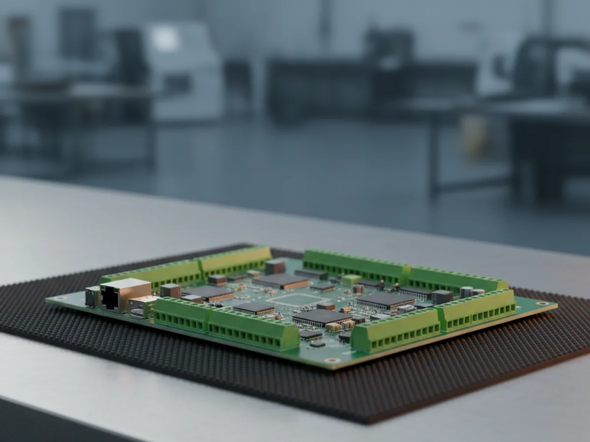
A GRBL style board holds the firmware, the motion planning and often the stepper drivers on one card. Send it G-code over USB, or run it from an offline pendant with an SD card, and it does the rest. For a three axis router, a laser engraver or a small mill this is usually all that is needed, and the offline option means a PC crash cannot ruin a job.
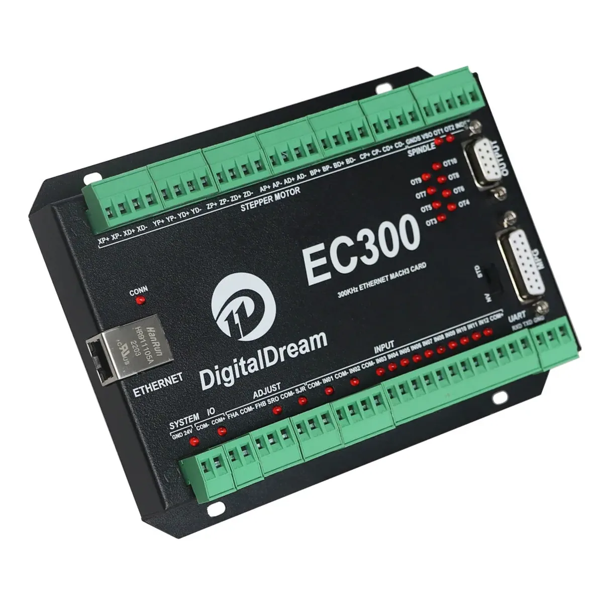
A motion controller is a different architecture. The PC runs control software such as Mach3 and does the interface and the look-ahead, while the controller generates the actual step pulses in hardware. That split exists because a general purpose operating system cannot be relied on to produce evenly spaced pulses at high rates, and uneven pulses show up as poor surface finish and lost steps.
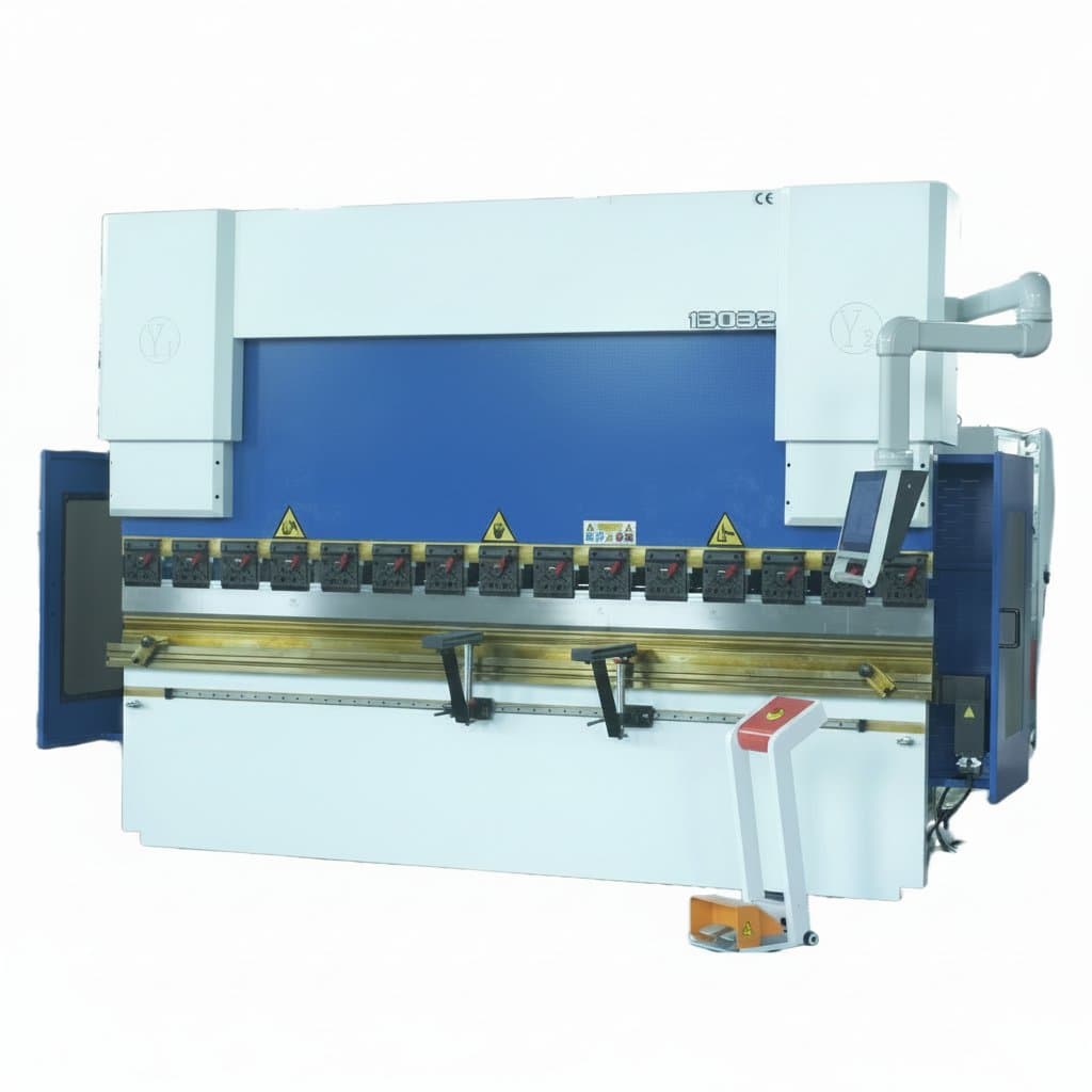
The practical dividing line is axis count and speed. Three axes on a modest machine suits an all-in-one board. Four, five or six axes, higher feed rates, or a machine where a missed step is expensive, points at a dedicated motion controller.
| GRBL style board | Motion controller | |
|---|---|---|
| Where motion is planned | On the board | Split: PC plans, board pulses |
| Needs a PC while cutting | No, offline option common | Yes, running the control software |
| Typical axes | Three | Four to six |
| Drivers | Often integrated | Usually external |
Pulse rate is the number that limits feed rate
Controllers are quoted in kilohertz, and that figure is the ceiling on how many step pulses per second the board can produce. It matters because your maximum feed rate is that pulse rate divided by the steps needed per unit of travel, and that in turn depends on motor steps per revolution, microstepping and the pitch of the screw or the pulley ratio.
The trap is microstepping. Raising it from eight to thirty-two smooths motion and quarters the top speed available from the same pulse rate. Machines that mysteriously will not rapid faster than a crawl are often set to high microstepping on a modest controller rather than short of motor torque.
Work the sum through before buying. If the arithmetic leaves no headroom, either a higher rate controller or lower microstepping is the answer, and the second is free.
USB or Ethernet, and where noise gets in
USB is simple, universally available and electrically fragile in this setting. A CNC machine is an efficient noise generator: stepper drivers switch hard, and a VFD driving a spindle radiates and conducts a great deal of interference. USB has no galvanic isolation as standard, so noise that gets into the cable can drop the connection mid-cut.
Ethernet is the more robust choice on anything with a VFD spindle or long cable runs, because the interface is transformer isolated by design and tolerates a noisy environment far better. It also lets the controller sit near the machine and the PC sit somewhere sensible.
Whichever you use, the wiring practice matters as much as the interface. Keep signal cable away from motor and spindle cable, use shielded cable for the motor leads with the shield grounded at one end only, and give the VFD its own filtering. A machine that is unreliable on USB is usually telling you about its wiring rather than about USB.
The stop circuit belongs in hardware
Most of these boards offer an emergency stop input, and it is worth being clear about what that is. A software input tells the controller to halt, which is useful and is not a safety function, because it depends on the controller still working to act on it.
A real emergency stop removes power from the things that can hurt someone, through a hardwired circuit with positive opening contacts that does not rely on firmware being healthy. On a hobby or light workshop machine that usually means a latching mushroom button in the supply to the spindle and drives, wired so that it opens the circuit directly. The controller input is then a useful extra that also tells the software what happened.
The same logic applies to limit switches. Wiring them normally closed means a cut wire or a failed switch stops the machine, whereas normally open wiring means the same fault silently disables the limits and nothing tells you until an axis drives into its end stop.