


Constant voltage, constant current and the crossover
In constant voltage mode the supply delivers whatever current the load asks for, up to the limit, while holding the set voltage. Cross that limit and the supply switches to constant current mode: it now holds the current steady and lets the voltage fall to whatever value achieves that.
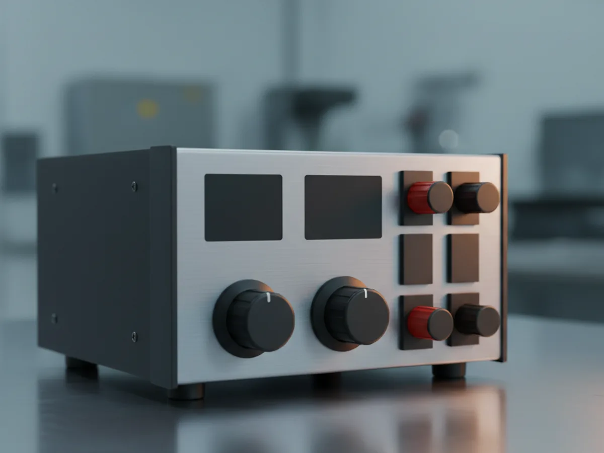
The front panel tells you which mode it is in, and that indicator is the most useful thing on the instrument. A board that should draw fifty milliamps sitting in constant current at your limit is a board with a short, and you know before anything is damaged.
The working habit is to set the voltage with the output off, set the current limit low, then enable the output. If the supply goes into current limit, something is wrong, and it has clamped the fault instead of feeding it. Powering a new board without a limit set is how a single solder bridge becomes a scrapped assembly.
| State | Means | Do next |
|---|---|---|
| Constant voltage | Load is drawing less than the limit | Normal operation |
| Constant current at your limit | Load wants more than allowed | Stop and check for a short |
| Voltage sagging at the load | Volt drop in the leads | Use remote sense or thicker leads |
| Protection tripped | Over voltage or over current fired | Investigate before resetting |
Linear or switching
A linear supply regulates by dissipating the difference between input and output as heat. That makes it heavy, warm and inefficient, and it also makes it extremely quiet electrically, with very low ripple and none of the high frequency content a switching converter produces.
A switching supply chops the input at high frequency, which is efficient and light, and puts switching noise on the output. For most digital and general work that noise is irrelevant, and for low level analogue, audio and sensitive radio work it is not.
The number to compare is ripple and noise, usually quoted in millivolts peak to peak. If the work involves amplifying small signals, a linear supply removes an entire category of mysterious interference. If it involves powering motors and logic, the efficiency and weight of a switching supply win easily.
Remote sense, and why the load sees less
Wires have resistance, and current through resistance drops voltage. At a few amps through thin leads the difference between the supply terminals and the circuit can be a meaningful fraction of a volt, and the display is showing what leaves the supply rather than what arrives.
Four wire remote sense fixes it. Two heavy leads carry the current and two thin leads measure the voltage at the load itself, so the supply raises its output to compensate for the drop and the circuit gets what was asked for.
Where remote sense is not available, shorter and thicker leads are the answer, and measuring at the load with a meter rather than trusting the panel is a good habit anyway. Panel meters have their own accuracy specification, and it is not the same as a calibrated instrument.
Programmable control and protection
A programmable supply accepts commands over a computer interface, which allows a test to sweep the voltage, step through a sequence, or log current draw over hours without anyone standing there. For repeatable testing that turns a manual afternoon into an unattended run.
Over voltage and over current protection are separate from the current limit and are worth setting. The limit regulates; protection trips the output off entirely, which is what you want when a fault could destroy something expensive rather than merely misbehave.
Two practical points. Multiple output supplies that track in series or parallel give higher voltage or current from the same box, which is often cheaper than a bigger single supply. And a bench supply is not an isolation transformer: it is not the tool for working on mains powered equipment, whatever its output rating.