




Momentary against latching, and the words listings use
A momentary switch makes contact while you hold it and returns as soon as you let go. A latching switch stays in whichever state you last pushed it to, so one press is on and the next is off. That is the whole distinction, and it decides the circuit around the button as much as the button itself.
The vocabulary on listings is the confusing part, because these parts are described with a set of translated terms that do not match UK usage. Self reset and self return both mean momentary. Self locking means latching. Push to make is a momentary normally open button, push to break is a momentary normally closed one. A listing offering both self locking and self reset versions of the same button is offering latching and momentary, at the same price, and the photographs are frequently identical.
Choose momentary whenever the circuit remembers the state for itself, which covers anything driving a relay latch, a contactor with a hold-in circuit, or a microcontroller input. Choose latching only where the switch itself must hold the circuit, such as a simple lamp or a fan running directly off the button. A latching button on a machine control is usually a mistake, because a power cut leaves it mechanically on and the machine restarts by itself when the supply returns.
| What the listing says | What it means |
|---|---|
| Self reset, self return, reset type | Momentary, springs back when released |
| Self locking, self lock, latching | Latching, stays where it was pushed |
| Push to make | Momentary normally open |
| Push to break | Momentary normally closed |
| 1NO 1NC | One normally open and one normally closed contact in the same body |
Panel cutout and why 22 mm is everywhere
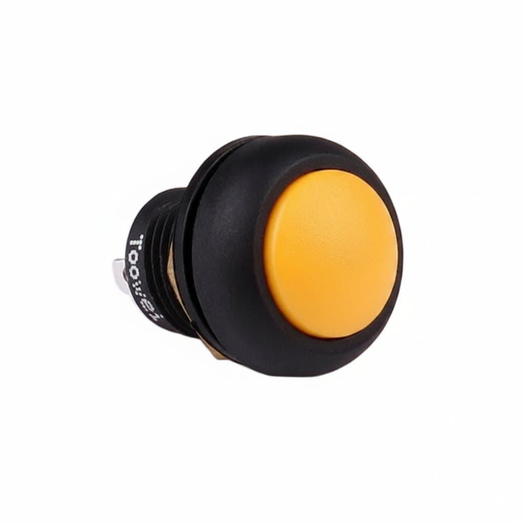
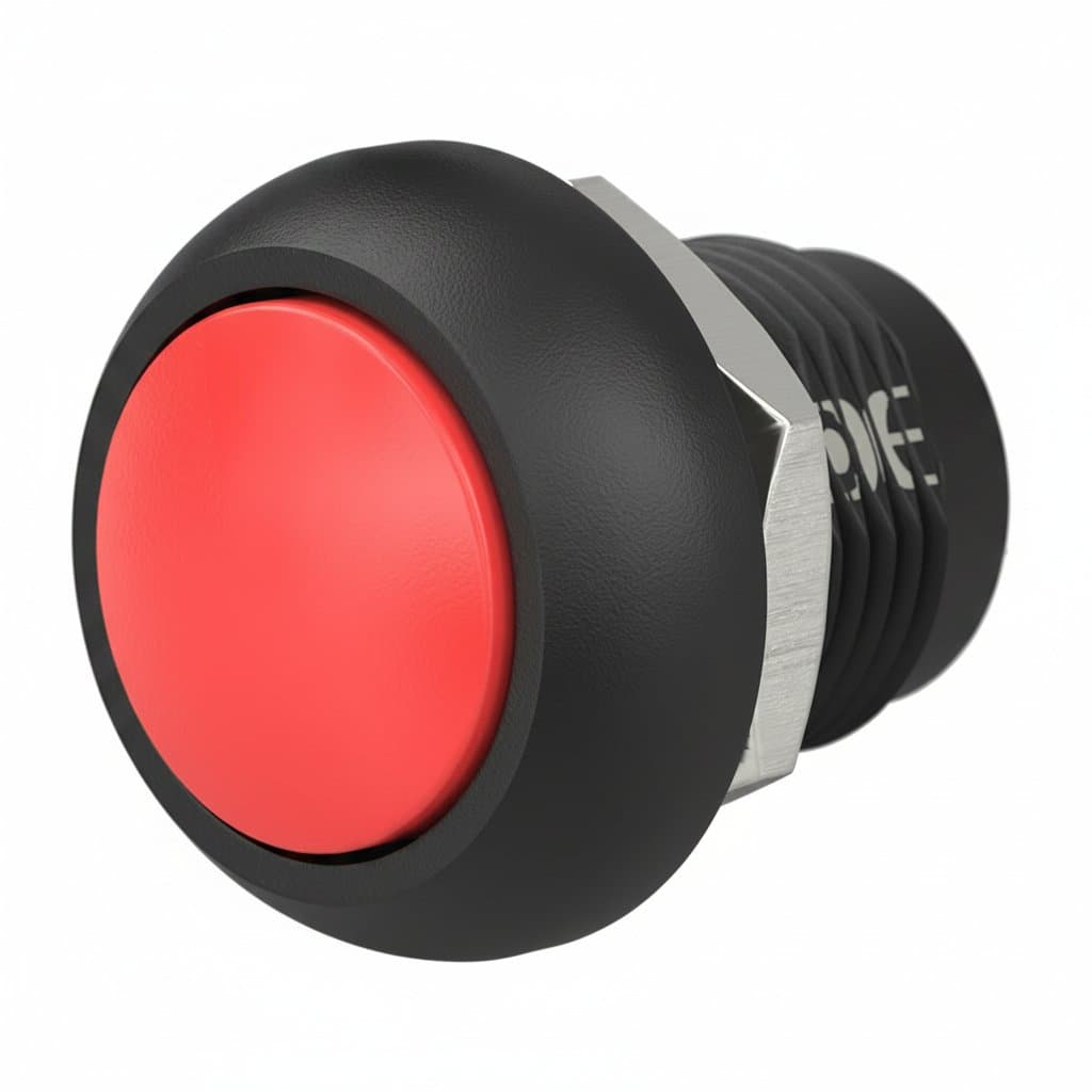
The size quoted on these switches is the mounting hole, not the button. A 16 mm switch needs a 16 mm hole and has a head slightly larger than that to cover it. The common series are 12, 16, 19, 22, 25 and 30 millimetres, and mixing sizes across one panel means more hole saw changes than the visual variety is worth.
The 22 millimetre size dominates industrial control panels because it is the standard cutout for command and signalling devices under IEC 60947-5-1, which is why buttons, selector switches, indicator lamps and emergency stops from different manufacturers all drop into the same hole. If a panel is likely to be extended or repaired by someone else, staying at 22 mm is the sensible default.
Panel thickness matters too. The threaded barrel behind the button has a finite length, and a switch specified for a 1 to 4 millimetre panel will not reach through a thick enclosure door with insulation behind it. So will the space behind: a button with two stacked contact blocks is considerably deeper than the head suggests, and running out of depth against a mounting rail is a common irritation.
Why a stop button has to be normally closed
In a conventional start stop station the start button is momentary normally open and the stop button is momentary normally closed, wired in series with the contactor coil. Pressing start energises the coil, an auxiliary contact on the contactor holds it in, and pressing stop breaks the series circuit and drops it out.
The reason stop is normally closed is not convention, it is fail safe behaviour. A broken wire, a loose terminal or a corroded contact in a normally closed stop circuit stops the machine, because the circuit it was holding closed is now open. Build a stop button as normally open and the same broken wire simply means the stop button no longer works, and nothing tells you until someone needs it. The machine keeps running and appears perfectly healthy.
An emergency stop is a different device and should not be substituted with an ordinary latching button. It is a mushroom head, it latches mechanically when struck and releases only by a deliberate twist or pull, and it uses positive opening contacts so the contacts are forced apart mechanically rather than relying on a spring. That last point is the one an ordinary push button cannot offer, and it is why an E stop cannot be improvised from a standard latching switch.
Illuminated buttons, IP ratings and terminals
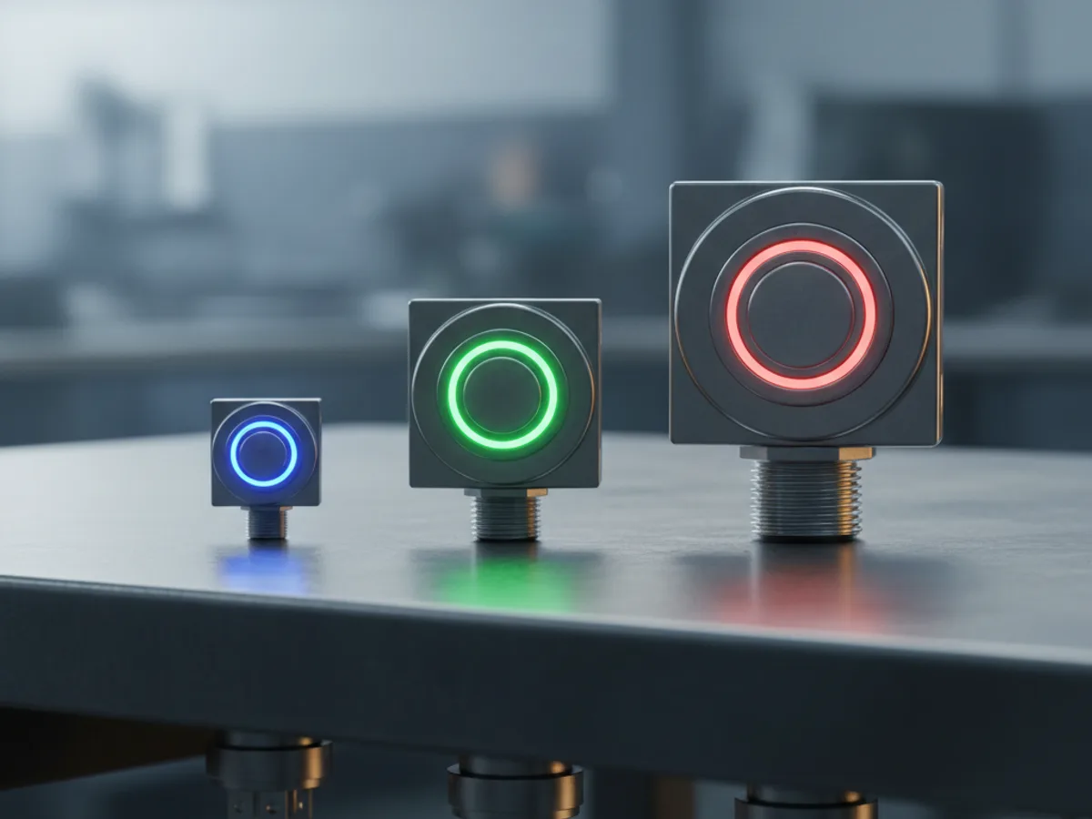
Illuminated buttons are supplied for a specific supply voltage, most often 12 V, 24 V or 220 to 240 V, because the LED and its dropper resistor are built into the body. They are not universal: putting 24 V through a 12 V illuminated button will not end well, and the LED in a mains version usually has its own resistor sized for mains and cannot be run from low voltage. Check the voltage of the illumination separately from the rating of the contacts, because they are two different specifications on the same part.
An IP rating on a push button describes the front face when it is correctly mounted with its sealing washer. The terminals behind the panel are not sealed and are not intended to be, which is why an IP65 or IP67 button still needs a suitable enclosure behind it. Fitting one in an oversize hole, or leaving out the gasket, loses the rating entirely.
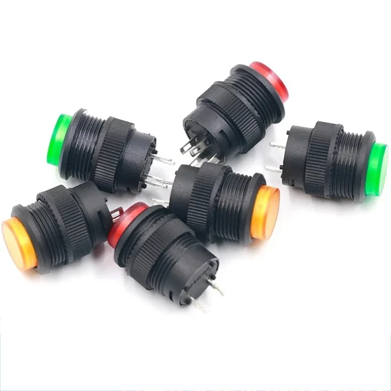
Terminal style is worth checking before ordering. Screw terminals suit panel wiring and take a ferrule or a spade. Solder lugs suit a one-off build. Quick connect spades suit production. Small twelve millimetre buttons frequently come with flying leads already attached, which is convenient for a prototype and a nuisance when you want to route your own cable.