Compel Groupgroup

Prototyping & Development

2 products available

Looking for reliable prototyping and development boards to validate your circuit designs? Compel supplies high-grade prototype PCBs and universal boards engineered for hardware verification, R&D testing, and pre-production runs. We stock professional-grade FR-4 fiberglass boards designed to withstand repeated soldering and thermal stress during component development.

Our range covers standard double-sided layouts with industry-standard 2.54 mm hole pitch and 1.0 mm hole diameters to fit standard ICs and passive components. Engineering departments and electronics manufacturers choose Compel because we provide consistent board thicknesses, reliable 1 oz copper weights, and multi-size kits that keep your laboratory stocked. Get your systems running quickly with components that match your exact testing tolerances.

2 products in Prototyping & Development

Selecting Board Material and Thickness for R&D

Industrial prototyping requires materials that resist warping under thermal load. Standard paper-based boards degrade quickly, which is why professional laboratories specify FR-4 fiberglass. This material provides the necessary mechanical strength and electrical isolation for high-frequency testing.

Board thickness also dictates how well the prototype integrates with physical enclosures. A standard 1.6 mm thickness prevents flexing when inserting heavy components or connectors.

  • Specify FR-4 fiberglass for superior flame resistance and mechanical stability.
  • Choose a standard 1.6 mm board thickness to ensure compatibility with card-edge connectors and chassis mounting.
  • Avoid thin, single-sided alternatives when testing multi-component systems that generate heat.

Matching Board Dimensions to Your Enclosure

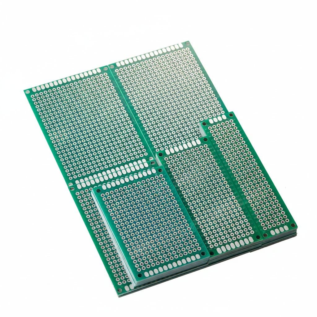
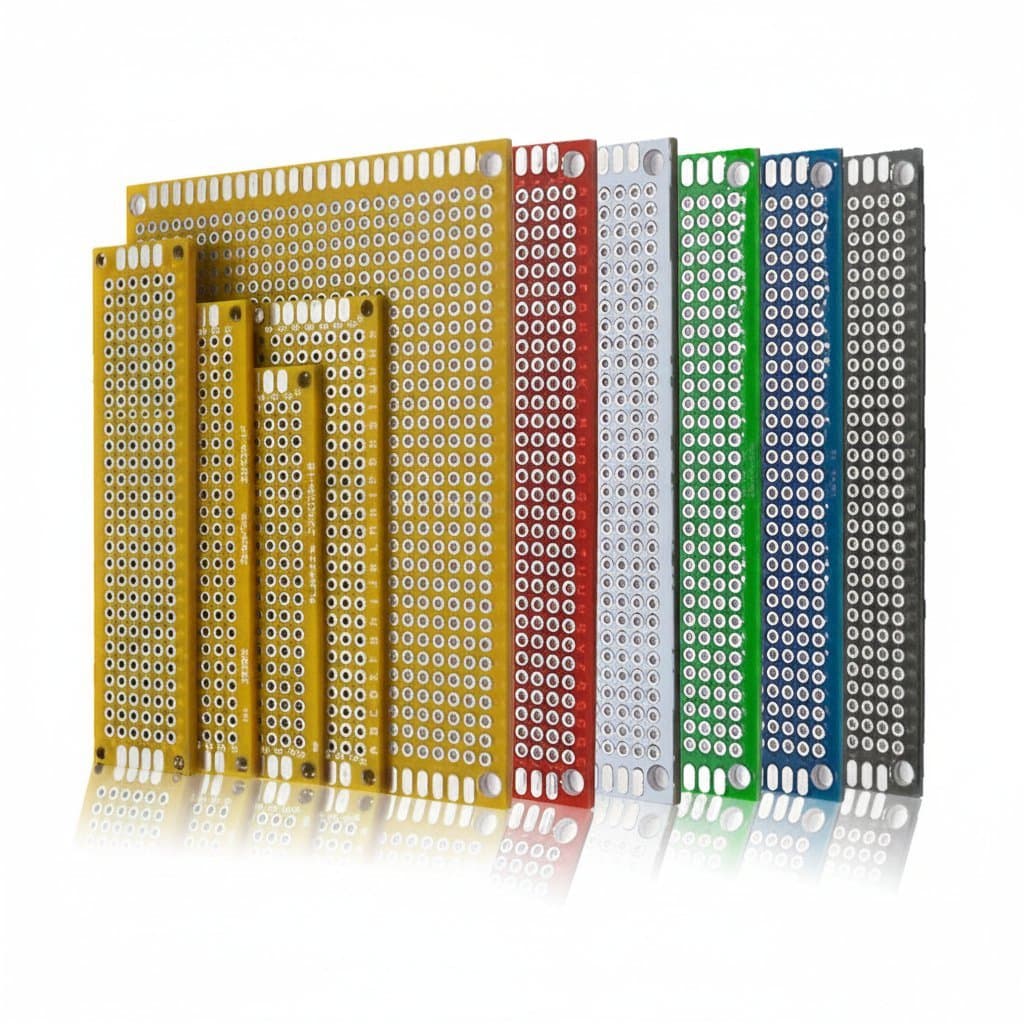
Selecting the right dimensions prevents unnecessary cutting and dust exposure in the lab. Compel stocks standardized sizes ranging from compact 2x8 cm strips up to larger 7x9 cm universal boards. Having assortments of various dimensions on hand allows engineers to choose the exact footprint needed for their prototype housing.

Double-sided copper layers allow for flexible routing on both top and bottom surfaces, which simplifies complex circuit paths in tight spaces.

  • Use 2x8 cm and 3x7 cm boards for slim inline filters, adapters, or sensor nodes.
  • Select 4x6 cm, 5x7 cm, or 7x9 cm layouts for microcontrollers, power regulation circuits, and denser component layouts.

Verifying Pitch and Hole Diameters for Component Compatibility

Standard electronic components rely on precise spacing to fit without lead bending. For breadboard-compatible testing, a 2.54 mm (0.1 inch) hole pitch is the industry standard. This spacing matches common dual in-line package (DIP) ICs, pin headers, and discrete passives.

  • Look for a 1.0 mm hole diameter to accommodate thicker diode leads and header pins without drilling.
  • Ensure the boards feature plated through-holes to guarantee electrical continuity between the top and bottom copper layers.
  • Verify 1 oz copper weight to handle typical signal currents and low-power distribution without trace overheating.

Buying guide

Choosing Prototyping & Development

Why should we specify FR-4 material over paper phenolic boards for industrial prototyping?
FR-4 fiberglass offers significantly higher mechanical strength and moisture resistance than paper-based alternatives. It handles repeated soldering temperatures without pad lifting, making it the standard choice for professional R&D environments.
Will standard pin headers fit the holes on these prototype PCBs?
Yes. The boards feature a standard 2.54 mm hole pitch and a 1.0 mm hole diameter. This layout directly accepts standard 0.1-inch male and female headers, DIP integrated circuits, and most discrete components.
What is the significance of the 1 oz copper weight on these boards?
A 1 oz copper weight, or approximately 35 micrometers thickness, provides reliable current-carrying capacity for standard signaling and low-power circuits. It prevents the copper traces from overheating or delaminating during normal testing and soldering cycles.
Are these universal boards suitable for high-frequency RF prototyping?
For basic RF testing, FR-4 is acceptable, but the grid layout of universal prototyping boards introduces parasitic capacitance. They are best used for digital logic, analog sensor conditioning, and power distribution prototypes. For microwave frequencies, custom-etched solid ground-plane boards are recommended.